3DESIGN
3.1 Wire Ropes
A wire rope is made up of a number of fibre or
steel wire strands laid helically around a core. The
strands themselves are composed of a number of
wires laid in various geometrical configurations.
Ropes are manufactured from steel wires which
are drawn from steel rods melted in open– hearth
or electric furnaces. The wire rope construction,
types and other terms used in this guideline are
described in the glossary.
3.1.1 Rope geometry
One of the basic challenges in the design and
construction of ropeway is to determine the shape
of curve of the loaded rope and to calculate the
precise forces acting upon it.
The shape of the rope curve is influenced by the
weight of the rope, the weight of the trolley that
slides upon it, the load in the trolley, wind load,
the friction developed on the supports (towers)
and the braking friction at rope or at the stations
during stoppage and icing (in cold places). In
each case, the curve has to be determined for
maximum and minimum conditions i.e. for rope
only and the line fully loaded. In these conditions,
the maximum sag of the rope and the bending
angles due to load on the supporting towers
at the two ends must be evaluated. Each rope
is exposed to tension caused by initial stresses
due to tension weight, the rope's own weight and
the weight of the loaded trolley at its maximum
carrying capacity (120 kg in the case of gravity
ropeway). The shape of the curve varies according
to the way the rope is fixed, its alignment, angle
of inclination and the number of spans (if the
gravity ropeway has more than one span).
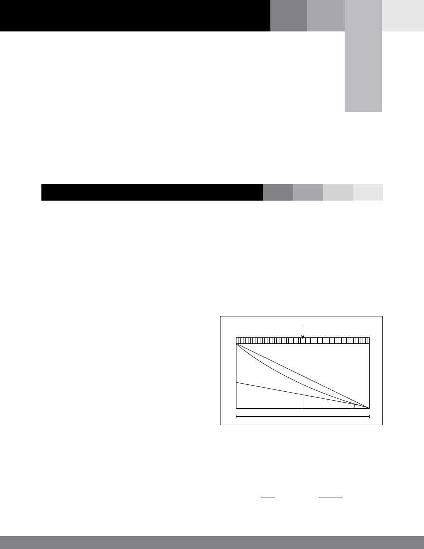
A) Uniformly distributed load along the rope span in
plan
w
4b
h
h-4b
y|
y1
I
x
β
Figure 14: Uniformly distributed load along the rope span in plan
In the above diagram,
y = y1+ y|
Where y1 = 4bx2 and y| = (h-4b)x
l2 l
17